Digital Analytics
Digital Analytics
For a given boat design, BOAT3D estimates the forces on a hard-chine planing boat using an added-mass analytical approach and some empirical rules. It solves the laws of motion for the predicted trajectory of motion of the boat. The boat moves with 3 degrees of freedom, lunge, heave, and pitch. BOAT3D lets you
----estimate the speed you will obtain from a particular design for a given engine/propeller thrust.
----also lets you estimate the accelerations imposed on the boat occupants at a particular speed in a particular sea condition, and the amplitudes of the heaving and pitching responses to the sea. The sea simulation was developed by the original author Peter R. Payne with assistance from his colleague J. D. Pierson and using earlier literature.
CAVEAT: Since the roll and yaw degrees of freedom are not considered, BOAT3D cannot tell you anything about roll or turning stability. Also, for good results the boat must be partially or fully planing, meaning that the length-based Froude number must be at least 0.6. ---- the boat is beyond displacement speed and at least in the semi-planing regime. Also, although I realize that most planing boats have "strakes" which have some effect on boat performance, BOAT3D does not take this into account. Water separation is assumed to occur at the chine.
After simulating a boat test run, the user can call up the output screen and manipulate it in various ways to look at results. In the following, the user is showing numeric values of variables at 127.564 seconds into the run, the position of the boat and the water at this time, and coincidently, a plot of vertical acceleration in G's at the center of gravity of the boat vs time (many different variables can be plotted, up to 6 at one time).
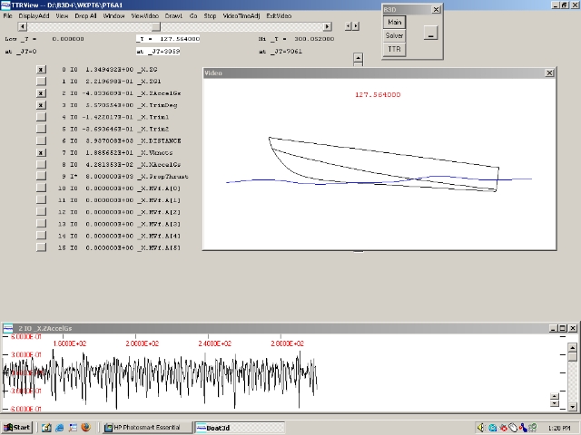
The boat graphic is within what is referred to as the "video" window. The user could single-step time to explore what is happening just before or just after 127.564 sec, or he could click on "Go" and the boat and waves would move (with a choice of real-time or slow-motion). This graphic feature, new in 2008, allows the user to gain a better understanding of what is going on in "slamming" or other such simulated events.
To give a prospective user more of a hands-on feel for this "video" window we provide a download of it in the form of the BOAT3D Demo Viewer along with some typical boat test runs in condensed form.
When working with the full BOAT3D program (not the Demo Viewer) the user can also transfer selected results to our graphics utility program EDTECH for plotting or further analysis. One of the pre-planned EDTECH printed outputs is as follows: The user may select up to 8 "snapshot" times for output of detailed force information. The program draws a snapshot of the boat's position with water surface indicated at each time, and the program gives its estimate of how water forces are distributed along the length of boat.
In the above example the solid line plot represents the total vertical lb force of the water on a boat segment (the boat is divided into 40 cross-sectional strips). The intermittent line plot represents that from the added-mass water impact force (the difference represents buoyancy). (Both lines are adjusted at the stern by the Payne "Dynamic Suction" effect.)
Various types of analyses can be performed. In one typical case (with 2 degrees of freedom) the user might specify flat calm water and a gradual increase (linear with time) of the speed over many simulated minutes. The program output estimates the boat trim angle, height of CG relative to sea level, and horizontal resistance force obtained at various speeds. If the analysis is performed with uniform waves, an estimate of the boat's performance in a particular wave type at various speeds is obtained. Similar analyses can be performed with 3 degrees of freedom by gradually increasing the propulsion thrust.
With random waves a simulation run with 3 degrees of freedom at constant thrust or optionally, propeller rpm, is normally performed. The program then analyses the results and provides you with a statistical summary of boat behavior. This includes average speed and resistance force, and information on vertical acceleration and heaving and pitching oscillations. The vertical acceleration results provide a measure of ride comfort. As mentioned above, besides looking at statistics it is important to look at individual "slamming" events, etc., to get a feel for what is happening.
Aeronautical engineer Peter R. Payne began designing and building fast experimental boats as early as the 1960's. He tested them in the Chesapeake Bay near his home. There were a number of unconventional catamarans in the 60's followed by a series of very unconventional monohulls called Sea Knifes in the 70's. Inspired by work of his friend and colleague J. D. Pierson of the Grumman Corp., Peter began to develop the BOAT3D program starting in the 1980's and ending with his untimely death in 1997. Peter used an augmented BOAT3D program to design his last experimental boat, the Dynafoil(tm). Digital Analytics' EDTECH program was used as the graphics tool for all BOAT3D graphical output.
The PAYNE DYNAFOIL(tm)
BOAT3D is one of several independently developed computer codes which have historically been described as "non-linear strip methods", etc.
The last version of BOAT3D which Peter published was numbered 2.5, and there was a gap of years in development after this.
After Peter's heirs graciously allowed Digital Analytics to continue developing BOAT3D, version 3.0 was created in 2003. The language was changed from Microsoft Basic for DOS to Borland Delphi Pascal for Windows and some mathematical re-structuring was done, requiring it to be cast into a DMSolver format. This was immediately followed by version 3.1.
In 2007 I changed certain geometrical and computational details so that the shape of the boat's bottom does not always have to conform to the straight-line rule, that is, the cross-sections (frames) do not necessarily have straight lines from the keel to the chine. This version was designated 4.0 because so many internal details were changed, although the user interface was almost like that for 3.1.
In 2008 I added several useful user interface changes including the "video" window shown above, and I made certain adjustments to the internal equations to make the methodology more robust. The boat may now optionally have double chines.
With each new version of BOAT3D with major simulation changes (3.0, 3.1, 4.0, 4.2), I have developed a technical paper which (a) describes important technical features of and changes in the BOAT3D methodology, and (b) shows in detail how BOAT3D results compare with experimental results. There is no simple answer to the question "How accurate is a BOAT3D simulation?" and the technical paper is an attempt to provide this type of information. There is also a newer addendum to the technical paper showing some comparisons with experimental drop tests.
In 2009 another feature was added to version 4.2 to give 4.3. As discussed in the technical paper, discrepancies have sometimes been noted between simulated and experimental results for boats travelling at semi-planing speeds close to the lowest speed at which successful simulation is possible (this is at length-based Froude number = 0.6). For 4.2 we added several empirical details which improve agreement in these lower-speed cases, and for 4.3 we added the final detail, but 4.3 is virtually the same as 4.2 for simulation at higher planing speeds.
4.4 is 4.3 with the "boat levelers" (trim tab) feature reactivated based on Peter Payne's original work. For 4.5 an additional more-direct method of defining the curvature at the cross-sections (frames) was added. Currently the version is 4.53. From 4.5 there are changes in this have to do with output of data to the user. There are some internal file format changes, and new capabilities for the user to output bow-to-stern profiles of force. There are bug-fixes. In V4.53 there are basically 2 changes, first, there is an internal change allowing some parallel processing so the simulation runs faster on any machine with 2 or more cpu "cores". Second, the SETUP installer program and copy protection were updated to resemble the ones for our other software.
BOAT3D and its utilities are standard Windows programs. RAM requirements are very moderate, but fast cpu speed and large disk capacity are beneficial.
As in earlier versions, the BOAT3D planing boat shape can be generated by specification of parameters for mathematical functions (developed by Payne) describing the shapes and positions of chines and keel. A trial set of parameters can be used to generate a drawing of the boat with the static waterline determined and shown in the drawing.
Also, in the new versions, users can enter their specific keel, chine, and gunwale coordinates from their existing boat design and if desired, specify curvature in the cross-sectional shape of the bottom. Much use is made of cubic splines, and there is a "smoothing" technique involving these.
The user specifies boat weight, CG position, and radius of gyration. If propeller details are being used, these are also specified.
All boat shapes are hard-chine.
Propulsion Specification Options are:
Various water surface conditions can be set such as flat calm water, uniform waves, or random waves following the Pierson-Moskowitz-Bretschneider energy density spectrum. Either head or following seas are specified.
For a given specification the program estimates the forward boat speed (3 DOF cases), trim angle, height of CG relative to sea level, and horizontal pressure and skin friction resistance forces, as well as horizontal and vertical accelerations and first and second time derivatives of trim. These and other results are written to a file for later plotting or other output.
If you have an interest in BOAT3D, I would be glad to answer any questions by e-mail or phone.
Francis Dail Singleton, PhD